On the exciter shorten the following coils: L301/L311, L302/L312, L303/L313, L304/L314, L305/L315, L306/L316 and L307/L317. The older models have paper coils and are somewhat easier to modify but tend to slip and require Teflon inserted between the slug and coil sleeve. The later models use plastic coils and are preferred because you don't have the slippage. The plastic and paper have different number of turns.
Paper Coil - 19D416859G4
Plastic Coils - 19D430230G4
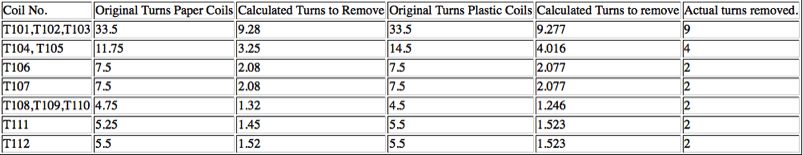
To calculate the number of turns to remove
• (174-150.8)/2+150.8 = 162.4
• 162.4/224.6 = 0.723
• 0.723 times the original No of turns gives the calculated turns to remove
• For example T101 has 33.5 turns and .723 times 33.5 equals 9.28
The taps are left unchanged
If L102 is 27 micro henry, it should work fine, if is is 38 micro henry, replace it with a .22 micro henry
Tuning Excitor
You can increase the power output 40mw by removing the resistor between T112 and RF Jack and replacing R147 (the resistor satnding on it end across from T111) a 36 ohm resistor with a 1/4 watt 10 ohm resistor
Tuning the exciter using a spectrum analyzer
The example I will use is 223.38. The fundamental frequency is 224.38/12 or 18.698 Q106 triples the frequency by amplifying the second harmonic to 56.095. Q107 doubles the frequency to 112.190 by amplifying the first harmonic. Q108 doubles again to 224.380.
Using a sniffer, set the spectrum analyzer to approximately 55 MHz – 57 MHz . Sniff around T101 and tune T101, T102, and T103 for maximum. Next move up to 112.190 and tune T104 and 105. Now move to 224.38 and Tune T106-T112.
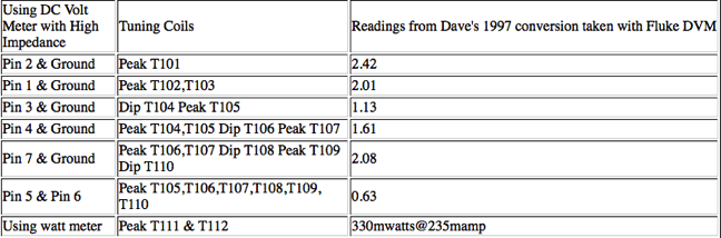
Use the procedure above to get a power measurement and tune for maximum output power. You can also tune as per the manual once you do the above procedure to get meter readings.
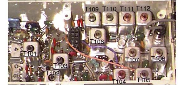
When modifying the coils, it is suggested that you remove all 15 cans. Use a hot iron and solder wick. Mark one leg of each coil and a corresponding pin hole on circuit board with a magic marker so you can replace the coil correctly. Remove coils one at a time, modify the coil, replace the coil and can. These coils have 4 connections to the circuit board
T101, T102 and T103 are identical and pictured above. Remove 9 turns for the top of the coil. Use a knife to scrape the wire so you can re-solder the wire to the leg.
T104 and T105 pictured above require 4 turns removed. Count 4 holes in both legs. Use your solder iron to seat the wire into the plastic leg. It helps to cut the wire but be careful not the cut the wire too short. These coils have 3 connections to the circuit board.
This is coil T106. The rest of the coils are simular to T106 and you remove 2 turns from coils T106 - T112.